

A Practical guide to GPS, WAAS, ILS and VORs
The following is a free Pilot lesson on the national airspace system NAS covering VOR ILS GPS and WAAS. A perfect tool for IFR student pilots: Make sure you check out the references section at the bottom of this lesson for more information.
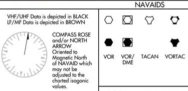
The (NAS) navigation services are based on a combination of ground-based and satellite-based services. In the future, navigation services will continue to be based on a combination of ground based and satellite based services for all phases of flight; although ground-based NAVAIDS infrastructure will be reduced (VOR MON).
VOR VHF Omni Range
Today, VORs still provide the backbone for our airway system. Although GPS is often used in place of the VORs, the FAA has committed to keeping an “operation contingency” VOR network as a failsafe in the event of a large scale GPS outage. VORs are also used to define holding points and non-precision approach procedures.
- A VOR is a ground based radio NAVAID.
- Requires an airborne component (the VOR receiver and a way to display the course data (CDI HSI RMI etc.).
- VORs operate within the 108.0 to 117.95 MHz frequency band and have a power output necessary to provide coverage within their assigned operational service volume.
- DME is often combined with VOR facilities and provides “slant range” distance from the NAVAID
- Most VORs have AM voice broadcast ability, each VOR has it’s own Morse code identifier that must be used to identify the station prior to using it.
- Some VOR equipment decodes the identifier and displays it to the pilot for verification to charts, while other equipment simply displays the expected identifier from a database to aid in verification to the audio tones
- You should be familiar with your equipment and use it appropriately
- If your equipment automatically decodes the identifier, it is not necessary to listen to the audio identification
- VOR receivers must be tested within 30 days prior to using them on an IFR flight.

How Does VOR Work?
VORs work on the principle of the phase difference in two radio signals.
You can get your mind around this concept by thinking of a tower with two lights on it. One light rotates at a constant rate around the tower but has a very narrow beam so that it can only be seen by the viewer just as the beam passes the viewer’s position. This is known as the (Variable Signal)
The other light flashes and can be seen in all directions (an omnidirectional light in our example), but here’s the magic, the light only “flashes” when the rotating light passes magnetic north. This is known as the (Reference signal).


So, if you know how fast the rotating light is moving, you could start a timer when the omnidirectional light flashes (reference signal), and then note the time when you see the rotating beam (variable signal.) Then, with some basic, math you’ll know your bearing from the station.
Here’s just an example so you can better understand the idea. If the light takes 60 seconds to make one rotation, let’s start our timer when we see the flash.. Wait for the light… Now STOP.. 30 seconds. So, if the flash was as the beam passed north, we know we are south of the station!
That’s how a VOR works. A rotating directional signal is broadcast from the VOR, while a second (omnidirectional) signal is broadcast only when the rotating signal passes north. The VOR receiver in your aircraft measures the time—or phase—difference in these two signals and comes up with the bearing—or radial—from the station.
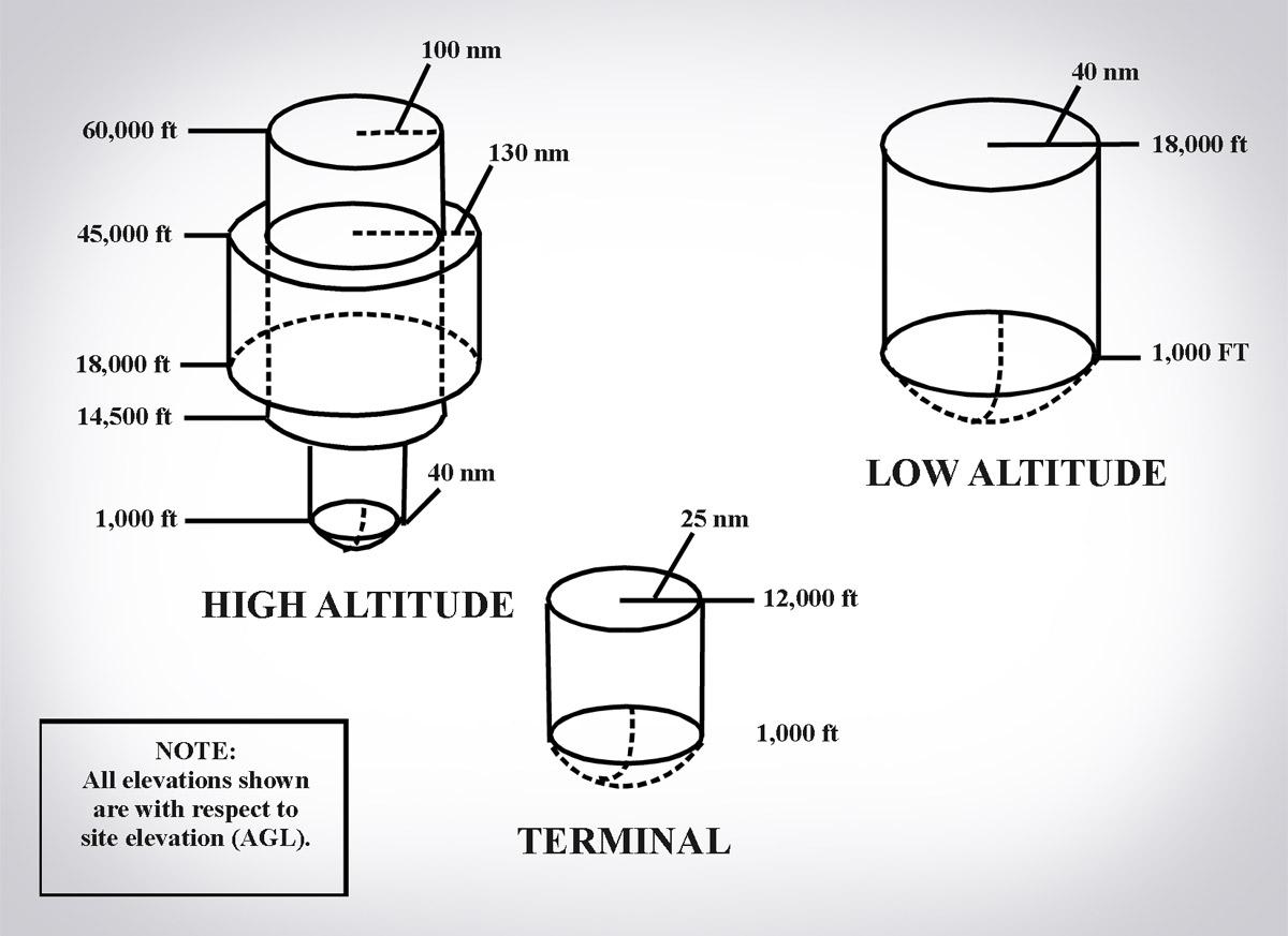
VOR VHF Omni Range Standard service volumes and types of VORs.
VOR VHF Omni Range: Testing requirements
Sec. 91.171
VOR equipment check for IFR operations.
(a) No person may operate a civil aircraft under IFR using the VOR system of radio navigation unless the VOR equipment of that aircraft–
(1) Is maintained, checked, and inspected under an approved procedure; or
(2) Has been operationally checked within the preceding 30 days, and was found to be within the limits of the permissible indicated bearing error set forth in paragraph (b) or (c) of this section.
VOR tests:
- FAA-operated or approved test signal or a test signal radiated by a certificated and appropriately rated radio repair station or, outside the United States, a test signal operated or approved by an appropriate authority to check the VOR equipment (the maximum permissible indicated bearing error is plus or minus 4 degrees);
- Use, at the airport of intended departure, a point on the airport surface designated as a VOR system checkpoint by the Administrator, or, outside the United States, by an appropriate authority (the maximum permissible bearing error is plus or minus 4 degrees);
- If neither a test signal nor a designated checkpoint on the surface is available, use an airborne checkpoint designated by the Administrator or, outside the United States, by an appropriate authority (the maximum permissible bearing error is plus or minus 6 degrees); or
- If no check signal or point is available, while in flight–
(i) Select a VOR radial that lies along the centerline of an established VOR airway;
(ii) Select a prominent ground point along the selected radial preferably more than 20 nautical miles from the VOR ground facility and maneuver the aircraft directly over the point at a reasonably low altitude; and
(iii) Note the VOR bearing indicated by the receiver when over the ground point (the maximum permissible variation between the published radial and the indicated bearing is 6 degrees). - (c) If dual system VOR (units independent of each other except for the antenna) is installed in the aircraft, the person checking the equipment may check one system against the other in place of the check procedures specified in paragraph (b) of this section. Both systems shall be tuned to the same VOR ground facility and note the indicated bearings to that station. The maximum
permissible variation between the two indicated bearings is 4 degrees.
(d) Each person making the VOR operational check, shall enter the date, place, bearing error, and sign the aircraft log or other record. In addition, if a test signal radiated by a repair station, as specified in paragraph (b)(1) of this section, is used, an entry must be made in the aircraft log or other record by the repair station certificate holder or the certificate holder’s representative certifying to the bearing transmitted by the repair station for the check and the date of transmission.
VOR VHF Omni Range: Limitations
Line-of-Sight:
- The range varies proportionally to the altitude of the receiving equipment
- This means the farther from the station, the higher you must be
- See Standard Service Volume (SSV) for more range restrictions
Reverse sensing:
- Reverse sensing flying TO a station with a FROM indication or a FROM with a TO indication
Cone of Confusion
- OBS Calibration errors
- Error between radial selected and the one shown in the course selection window
- Propeller Modulation: (If signal passes through prop, arc modulation can be changed CDI needle may fluctuate as much as plus or minus 6°

Tracking VORs: Wind corrections

Distance Measuring Equipment (DME)
- Paired pulses at specific spacing (interrogation) are sent to a ground station from the aircraft via the antenna
- The ground station (transponder) sends the same pulses back to the aircraft at a different frequency
- Time it takes is interpreted as the distance, usually in Nautical Miles (NM)
- Distance is measured in slant range (not horizontal range!) but some units can correct this Slant range error minimized at lower altitudes
- Operates on the line-of-site principle
- Reliable up to 199 NM accuracy of better than 1/2 mile or 3% of the distance, whichever is greater (more accurate)
- Due to the limited number of available frequencies, assignment of paired frequencies is required for certain military non-collocated VOR and TACAN facilities which serve the same area but which may be separated by distances up to a few miles
- DME paired with a VOR constitutes a VORTAC
- Can be identified every 30 seconds or about every 3rd to 4th VOR identification
- Required above FL 240 when VOR navigation required (under IFR) as per FAR 91.205(e)
- If DME fails above FL 240, continue to next airport where repairs or equipment replacement can be done (must still report as per AIM 5-3-3)
- GS values, if displayed, are only accurate when flying directly to / from the station

Service volume applies:
Note that Standard Service Volume (SSV) does not apply to airways as they’ve been certified at their respective distances
Frequency:
960 MHz to 1215 MHz in accordance with ICAO Annex 10
ILS (Instrument Landing System)

ILS components:

ILS (Instrument landing system): Localizer coverage area:
ILS Marker Beacons:

Approach Lighting Systems (ALS)

GPS (Global positioning system):
- Nominal 24 GPS satellites in low earth orbit
- Each satellite transmits data message
- Airborne receiver processes message to determine position/velocity/time
- Navigation function; either in FMS or in GPS (stand-alone)
- Linear, not angular
GPS (Global positioning system): Space


GPS (Global positioning system): Control
- Ground based monitoring stations
- Master control stations
- Ground antennas
- Ensures accuracy of the atomic clocks
GPS (Global positioning system): User

RAIM (Receiver autonomous integrity monitoring):
- Calculates your position vs. satellites to determine if sufficient for navigation
- Considers known satellite failures
- RAIM check for approaches (not en-route)
- RAIM check is required. AC 90-100, para 8(5)
- RAIM minimum of 5 satellites with satisfactory geometry
- Enhanced RAIM capability called Fault Detection and Exclusion (FDE). minimum of 6 satellites
- Preflight predictions ensure that sufficient satellites will be in view during the approach to enable GPS receiver equipment to perform RAIM and FDE.
WITH APPROVED GPS, I CAN:
- File RNAV
- Fly an LNAV approach
- Fly an RNP/RNAV approach
- Fly a GPS approach
- …but I can’t file a GPS alternate
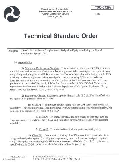
- …and GPS is supplemental
PRIMARY OR SUPPLEMENTAL NAVIGATION?
- GPS is considered supplemental
- TSO C-129 “Airborne Supplemental Navigation Using GPS”
- Must have equipage satisfactory for the route of flight
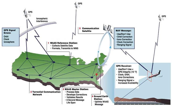
How WAAS works:
WAAS CAPABILITIES:
- Why WAAS?
- Enhances en-route navigation performance over GPS alone
- Enhances non-precision approach capability over GPS alone
- Allows WAAS equipped users to fly more than 2,891 published LNAV/VNAV procedures to minimums as low as 300 feet
- Allows WAAS equipped users to fly new LPV procedures
- Can use GPS for an alternate (LNAV only)
- Advanced missed approach
- Better than 99.99% availability of system
- 95% availability in CONUS of approach with vertical guidance
- 200’ minimum (maybe)
- WAAS specific approaches (LPV)
- 646 LPV approaches published, with 300 new expected in 2007
WITH WAAS, I CAN:
- Skip the RAIM check!
- Fly an LNAV/VNAV approach
- Fly an LPV approach
- Use GPS/WAAS entirely
- …and I can file a GPS alternate
- But using the LNAV minima line
- WAAS is not supplemental
- TSO-C146 “Stand-Alone Airborne Nav Using GPS Augmented by WAAS)
- TSO-C145 “Airborne Nav Sensors Using GPS Augmented by WAAS”

LOCALIZER PERFORMANCE WITH VERTICAL GUIDANCE (LPV)
- Flies like an ILS (but better!)
- Minimums down to 200’ AGL
RNP(Required navigational performance)

CHARTING WITH LPV MINIMUM LINE:

LAAS(LOCAL AREA AUGMENTATION SYSTEM)

TRANSPONDER:

References:
FAA AC20-138B Airworthiness Approval of Positioning and Navigation Systems